Gates and slots
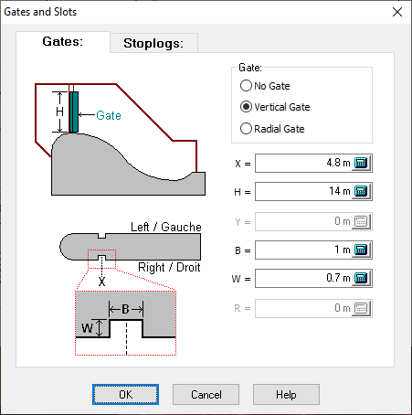
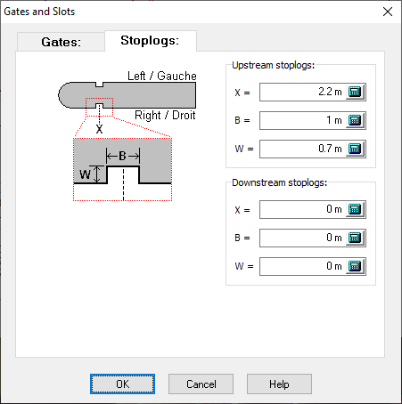
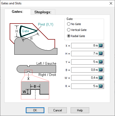
The Gates and Slots command positions the gates (Figure 49 A) and stoplogs (Figure 49 B) as well the thickness of corresponding slots, as shown in Figure 49. The slots cannot be located within the nose section of the pier. In addition, the slots for the gate must be located between the slots of the upstream and downstream stoplogs. To bypass the definition of stoplogs, all the corresponding parameters are set to zero. The user can also define a radial gate by selecting the corresponding type (Figure 49 C). The thrust on the radial gate is transferred to the pivot of the radial gate.

Figure 49 A

Figure 49 B

Figure 49 C