Geometry
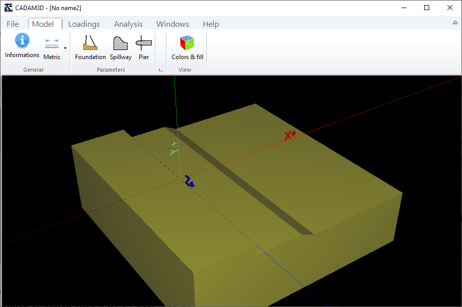
Figure 17 shows a typical 3D view of a foundation in CADAM3D. The basic assumption is that the foundation has a constant width along the Z-axis and that is sufficient to create its 3D geometry. Only the shape of the upper surface of the foundation is important in the stability analysis. It is therefore not necessary to define an assembly of closed segments in this case. For the 3D representation of the model, however, the software treats the foundation as a volume, with vertical walls and a horizontal base, as shown in Figure 17.

Figure 17
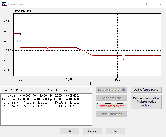
By activating the Foundation tab in the Model bar, a new window appears and allows the foundation to be defined. This window, shown in Figure 18, is similar to Figure 10 and defines the foundation upstream-downstream profile in the X-Y plane. The 3D geometry of the foundation, shown in Figure 17, is the result of the extrusion of the two-dimensional sketch of Figure 18.
To define the profile of the foundation using this window, it is necessary to first specify the position of the upstream and downstream boundary points. Next, the user can set segments (Linear segment, Arc of circle segment, Power equation segment & Polynomial equation segment) to connect the upstream origin point to the downstream end point.

Figure 18
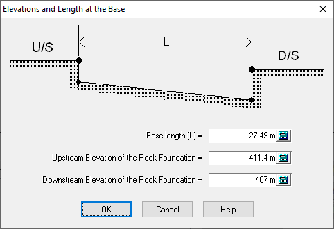
Information related to the position of the upstream and downstream points is entered using the Elevations and Length command that opens the window in Figure 19.

Figure 19
The distance between the upstream and downstream points and their elevations are the only information required. In CADAM3D, the origin of the horizontal axis (X=0) is located at the upstream initial point of the foundation as shown in Figure 18.
The Elevation of a given point is generally used in practical applications to define coordinates in hydraulic structures. In CADAM3D, it is not necessary to define a "datum" or to place the origin of the axis of the ordinates at the heel of the foundation. The user can enter the elevations of the given points directly as vertical coordinates.
The window is closed when the correct values are entered, and the OK button is pressed.

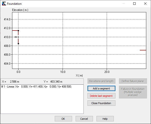
Figure 20
To define the exact profile of the foundation, the user must join the two previously defined points (U/S and D/S points) with a series of segments using the command add a segment (Figure 20) as many times as necessary. This activates a window that allows segments to be defined with predefined shapes (Linear segment, Arc of circle segment, Power equation segment & Polynomial equation segment). The user must specify all the segments except the last one, which will be defined automatically by the software by attaching the end point of the last segment to the end downstream point of the foundation using the command close foundation. Each defined segment is numbered and is shown on the screen throughout this process. Information about these segments is listed at the bottom left corner of the Foundation window.
Note: The definition of the foundation length is a vital element for the structural modeling. In fact, the length of the foundation corresponds to the horizontal distance between the upstream and downstream points where a gravity dam, a chute, a pier or a water intake is in contact with the foundation along this length. Any volume other than the four structures listed above (e.g. Added volumes) should not be considered in determining the length of the foundation. This is important when starting the modeling process. Failure to do so will lead to problems, particularly at the foundation-structure contact.